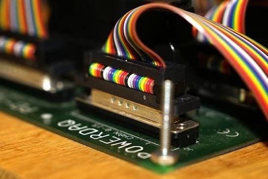
Every electronic product has at least one boundary where the circuit board must communicate with the world beyond its edge: a power input, a data bus, a sensor input, a display output. That boundary is served by a connector, and the quality of the connector decision influences not just the assembly cost but the product’s field reliability, its ability to survive the end customer’s environment, and the cost of warranty repair. PCB connector selection is rarely glamorous engineering, but it is engineering that matters.
The Range of PCB Connector Formats
The term PCB connector covers an enormous variety of products. Wire-to-board connectors bring cables from the outside world onto the board. Board-to-board connectors stack or join boards within an assembly. Edge connectors allow the board itself to become one half of the mating pair. Each format involves different mechanical constraints, different retention strategies and different reliability characteristics. The correct choice depends on the assembly process, the access available for mating and unmating in the field, and the environmental conditions the connector will face once the product is deployed.
Through-Hole Versus Surface Mount Mounting
Through-hole PCB connectors provide the strongest board retention because pins pass through the board and are soldered on the reverse side, resisting pull-out and insertion forces effectively. They suit connectors mated and unmated repeatedly, applications with cable pull loads, and vibration-prone environments. Surface mount connectors allow pick-and-place assembly in the same process as other SMT components, reducing manufacturing cost, but the solder joint bears the full mating load. For low-cycle, benign-environment applications SMT is appropriate; for high-cycle or high-force duties, through-hole or a mechanically locked hybrid is the safer choice.
Contact Rating, Pitch and Contact Count
Pitch Selection
Connector pitch — the centre-to-centre spacing of contacts — is the primary driver of contact count in a given footprint. Standard pitches run from 0.5 mm for fine-pitch signal connectors up to 5 mm and beyond for power connectors. Miniaturisation pressure drives designs toward finer pitches, but finer pitches bring lower current capacity per contact and greater sensitivity to co-planarity errors in soldering. For a product that must be serviced in the field, a connector with a pitch too fine for easy handling by service technicians creates a long-term support problem.
Current Rating and Derating
Contact current ratings assume specific conditions, typically a single energised contact at room temperature in still air. In a densely populated connector with several high-current contacts active simultaneously, the thermal environment inside the housing raises temperatures and reduces the practical current capacity of every contact. Reputable manufacturers publish thermal derating curves; applying them is not conservative practice, it is basic reliability engineering. Undersized contacts in power applications are among the most reliable sources of slow-burning field failures that are expensive to diagnose.
Locking and Retention Mechanisms
A connector that can be accidentally disconnected is a connector that will be accidentally disconnected, usually at the worst possible time. Latching mechanisms add a small cost and a small increase in assembly time, and they pay for themselves on the first field call they prevent. For applications where the connector is in a location that makes accidental displacement likely, where cable tension could pull a non-latching connector free, or where vibration is present, a positive locking mechanism is not optional. Some board-mount applications benefit from secondary retention hardware such as bracket screws that supplement the solder joint retention of the connector body.
When Standard PCB Connectors Are Not Enough
The consumer and industrial electronics market is well served by catalogue PCB connectors for benign indoor environments. When the product operates outdoors, on a moving vehicle, in the presence of dust and moisture, or in a temperature range beyond the typical minus 40 to plus 85 degree Celsius industrial rating, catalogue PCB connectors begin to show limitations. In such cases, PCB connectors with hermetic sealing, conformal-coated housings or extended temperature ratings must be evaluated. For the highest duty applications, the correct engineering answer is often to bring signals off the board through a proper circular connector shell that provides genuine IP67 sealing and the mechanical robustness of a threaded or bayonet coupling.
Circular Connectors as a Board Interface
Many electronic assemblies that live inside sealed enclosures or harsh environments use circular connectors at the panel to bring external connections to an internal PCB through a cable pigtail. This arrangement gives the PCB designer access to the full catalogue of standard PCB connectors on the internal connection while the external face presents a certified sealed connector to the user. Ranges such as MS connectors used as panel receptacles, terminated to a short internal loom that plugs into the PCB, combine the rugged environmental performance of a mil-grade circular connector with the design flexibility of conventional board-level interconnection.
The Indian Manufacturing Context
India’s electronics manufacturing sector has expanded dramatically under production-linked incentive programmes, with PCB assembly now occurring at scale across consumer electronics, industrial controls, medical devices and defence electronics. As product designs mature and move from imported designs to domestically developed ones, the connector specifications embedded in those designs need to reflect what is actually available from quality local sources. Established circular connector manufacturers in India including Allied Electronics Corporation provide not just the connectors themselves but application engineering support that helps designers make the transition from catalogue selection to application-specific solutions — support that offshore suppliers struggle to replicate across time zones and cultures.
Conclusion
PCB connector selection is one of those engineering decisions that appears simple and proves consequential. Work through the mechanical mounting method, current derating, locking requirements and environmental rating in sequence before committing to a product. Where the catalogue does not serve the application, a conversation with a connector manufacturer’s application engineering team is the most productive next step. Getting the connection right at the board edge is one of the most cost-effective reliability investments available to any product developer.